
3-Axis CNC portal machine
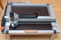
Affordable and easy to build multifunctional 3-axis CNC portal machine with a work area of 500 x 300 mm
Lots of DIYers have no problem building electronic circuits or programming a microcontroller without breaking a sweat. When it comes to mechanics however, even simple parts like a cover or a gearwheel can be beyond the realm of imagination. This has changed with the development of 3D printers, but these have their limitations too. While the most basic CNC mill may look like a drill press on steroids, 3D printing which produces shapes by additive deposition looks more sophisticated. CNC may look savage compared to a 3D printer but CNC machining is often a lot faster and the final accuracy and surface roughness of finished parts is much better. I don't have the intention to criticize 3D printing by mentioning this as 3D printing has its specific uses and advantages too and can produce shapes that are very difficult to make on a CNC machine.
Due to the emergence of 3D printing and the maker movement, a lot of mechanical parts like timing belts, gears, bearings, linear guides and so on, are easier to come by compared to a decade ago. The 3-axis CNC machine presented here is affordable and built around easy to get parts and materials. However, to build the machine from scratch, intermediate metalworking skills are required. Besides basic tools, you will also need a mitre saw which can cut aluminum, a drill press, a metal drill bit set, a step drill bit and a tap and die set. While not absolutely necessary, a small (mini) lathe will prove useful.
Compared to the usual CNC portal milling machine, this machine is notable for its frame. The frame not only adds mechanical rigidity but also allows easily replacement or height adjustment of the work area. The frame is also useful if you want to use the machine for other purposes than milling, engraving or drilling. If necessary, it is still possible to construct the machine without the frame, especially the aluminum profiles on the front and backside of the machine.
The work area is approximately 500 x 300 mm with a Z-axis travel of approximately 55 mm. The actual workspace area is somewhat dependent on the extension mounted on the X-axis. For now we have only a Z-axis with a spindle but an SMD pick and place head or a laser head might be another possible extension.
The linear guides and bearings are made by Igus. The same goes for the cable chains and the chainflex cables to the stepper motors and the limit switches. The stepper motors are Nema 17 types which are in our opinion more than powerful enough for this application. The belt is a 6 mm steel enforced GT2 timing belt.
All limit switches are NC types connected via optocouplers. As such, stepper motor currents and noisy spindles do not affect the limit switch operation. Both the X-axis and the Y-axis have two limit switches. The Z-axis has only a maximum travel limit switch. A minimum travel switch is not really useful here as the tool would already have crashed into the workpiece before a minimum switch could be activated. For additional safety and peace of mind we included a machine kill switch.
The spindle is a Proxxon LBS/E long neck drill/grinder. These are affordable and offer decent quality and allow for a more flexible Z-axis adjustment.
The machine is powered by a Meanwell SP-240-24 24 V 10 A power supply. An additional 12 V 5 A power supply is available for powering extensions. The electronics consist of a Synthetos TinyG controller and an optocoupler board. The TinyG offers an affordable and compact solution as no separate stepper motor drivers are needed.
Concerning CAM software, we tested CamBam and EstlCAM. While CamBam offers more options, EstlCAM is cheaper and more intuitive to novice users. Both software packages convert .dxf files to G-code files (.nc). EstlCAM offers an additional CNC control console which unfortunately does not work with the TinyG controller.
In order to control the machine and send G-code files we tested CNCjs and Chilipeppr. For initial testing and calibration, a simple terminal program like CoolTerm is more suitable.
You can check out the final result of this project where the Elektor logo is milled into a piece of 10 mm MDF board.
Diskussion (2 Kommentare)