
150169 MIDI Analyzer
Published in Elektor Magazine issue 7/2015 on page 78 Hardware usedProject PCB 150169-1
Hardware used
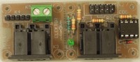
This circuit is basically not more than a DIN5 socket connected to our ECC bus to monitor and analyze midi signals. A second DIN5 socket is added as an optional output, but it can also be used for other applications. The single sided PCB (71.1 x 30.5 mm) is designed to easily separate this second DIN5 socket. A row of small holes make it easy to saw the PCB in to two parts, each with their own mounting holes (for M2 screws). The power supply voltage is delivered by the ECC bus (pin 9). Led D1 indicates the power supply is present or not. The input circuit is pretty much a standard MIDI application. We used a fast optocoupler (6N137) to interface the midi signal on K1 to the RX input of the ECC bus (K2). Pins 4 and 5 of DIN5 socket K3 are connected by two 220 Ω resistors to +5V and TX of the ECC connector respectively. When separated screw terminal block K5 can be used to connect pins 4 and 5 for MIDI purposes or all 5 pins through K4 for other purposes. A socket for K4 limits the chance of accidental shorts, so we mention this in the bill of materials (so instead of a header). A header was used on the prototype. We use our Arduino Shield 140009-91 to connect the little PCB to an Arduino UNO. Software is almost finished. In the photo you can see a first prototype. The PCB was made with our PCB milling machine. We engraved the negative of the topoverlay into the top side. To put it differently, only the components themselves and text are milled instead of everything else. This was part of an experiment if this could be done. It looked better than expected, but down side is the wearing of the milling bit. FR4 material is tougher than the copper layer! This is the reason copper planes can be seen from the top side. To spare the milling bit only the tracks, pads and vias are cut free by default. Another detail is R1, it’s pushed a bit sideways in our prototype. We used a DIN5 socket from Pro Signal, a smaller one is type MAB 5 SH from Hirschmann. The PCB is designed to handle two different styles.
Bill of materials
Resistor
R1,R2,R3,R4 = 220 Ω, carbon film, 5%, 0.25W
R5 = 1 kΩ, carbon film, 5%, 0.25W
Semiconductor
D1 = 1N4148
LED1 = LED, green, 3 mm
IC1 = 6N137, DIP8 (+ socket)
Other
K1,K3 = DIN socket, PCB, 5p, 180° (e.g. Hirschmann MAB 5 SH)
K2 = Header, 2x5, vertical, lead spacing 2.54 mm
K4 = Socket, 1x5, vertical, lead spacing 2.54 mm
K5 = Terminal block, 2-way, lead spacing 5.08 mm
Misc.
Want to build a project?
Bring your design to life with the Elektor PCB Service, powered by Eurocircuits. Upload the project files and order professionally manufactured PCBs or assembled boards through a proven European production platform.
Supporting KiCad, Eagle, Gerber, and ODB++ formats, the service is suitable for everything from prototypes and validation builds to series production and volume manufacturing.
Made in Europe. Fast. Reliable. Professional.
Diskussion (0 Kommentare)