
140257-1 GSM Break-out Board
GSM Modem Break-out BoardIntroduction:
GSM Modem Break-out Board
Introduction:
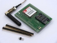
Another break-out board designed to provide easy interfacing of the well-known GSM/GPS module, SIM900A. SIM900A is a complete integrated chip for GSM/GPS modem functions.
It is a dual-band GSM/GPRS engine that works on EGSM 900MHz and DCS 1800MHz frequencies. The break-out board consists of a power section, SIM card slot, LED indicators and interfacing connectors. The board gives feasibility to use the SIM900A module with other application as per requirements. Its compact size and easy mounting feature makes it ideal for interfacing with small circuitry as well.
Break-out Board Specifications:
SIM900A Features and Specification:
Serial communication Specification:
Connectors:
Indicators:
Antenna:
SMA Adaptor Jack to Jack connector can be connected using short shielded cable to this point for connecting required antenna. GSM Antenna “ANT-GHEL2R-SMA” can be connected to adapter jack.
Power Section:
The power section is based on MIC29302WT high current, high accuracy, low-dropout voltage regulators. 5V to 12V dc supply can be applied to regulator through K3 interfacing connector. The circuit is designed to produce the 4.1V output for the SIM900A module and hence connected to VBAT pin of the module. Connector K1 can be used as a jumper to start the module (Short K1 if used in application circuit).
Testing Procedure:
Testing GSM Modem using AT commands:
If the device is powered up with a voltage less than 3.4V then module will respond automatically to the AT + CFUN command with a “UNDER –VOLTAGE WARNNING” message.
The AT+CPIN command can be used to check the status of the SIM. On entering this command into the hyper terminal the module automatically respond with the SIM status message as” NOT INSERTED” or
“READY” accordingly.
(See Attachements)
Introduction:
Another break-out board designed to provide easy interfacing of the well-known GSM/GPS module, SIM900A. SIM900A is a complete integrated chip for GSM/GPS modem functions.
It is a dual-band GSM/GPRS engine that works on EGSM 900MHz and DCS 1800MHz frequencies. The break-out board consists of a power section, SIM card slot, LED indicators and interfacing connectors. The board gives feasibility to use the SIM900A module with other application as per requirements. Its compact size and easy mounting feature makes it ideal for interfacing with small circuitry as well.
Break-out Board Specifications:
- 66.5mm x 49.5mm Size board
- Integrated power supply using high current LDO regulator
- Power ON and Net status LED indicator on board
- Standard 6 pin SIM card slot
- 2 x 24 pin micro header connector for interfacing.
- Modem ON pin / Jumper on board
- Antenna connector / SMA adapter
- Supply voltage range from 5V to 12V.
SIM900A Features and Specification:
- GSM and GPRS
- SMS and Data service
- Dual band 900MHz and 1800MHz
- Can be used for standard GSM Network
- Programmable General Purpose Input & Output.
- One audio channel includes a microphone input and a speaker output.
- Power down Mode
- Phonebook Management:
- Read contact, Add contact, and delete contact
- Messaging:
- Read Message, Send Message and Delete Message
- Call operation:
- Transfer call, Make a call, Holt a call, and answer a call
- Transmitting power
Class 1 (1W) at DCS 1800
- Support SIM card: 1.8V, 3V
- Serial port and Debug port
Serial communication Specification:
- Half duplex communication
- Full modem interface with status and control lines, asynchronous default baud rate of 9600bps
- Baud rate range from 1200bps to 115200bps
- Can be used with Standard AT commands or data stream.
- Uses Asynchronous communication
Connectors:
- K1 = Power ON jumper or switch
- K2, K3, K4, K5 = SIM900A interfacing connector
Indicators:
- LED1 = Power ON LED
- LED2 = NET status indicator
Antenna:
SMA Adaptor Jack to Jack connector can be connected using short shielded cable to this point for connecting required antenna. GSM Antenna “ANT-GHEL2R-SMA” can be connected to adapter jack.
Power Section:
The power section is based on MIC29302WT high current, high accuracy, low-dropout voltage regulators. 5V to 12V dc supply can be applied to regulator through K3 interfacing connector. The circuit is designed to produce the 4.1V output for the SIM900A module and hence connected to VBAT pin of the module. Connector K1 can be used as a jumper to start the module (Short K1 if used in application circuit).
Testing Procedure:
- Connect power supply to connector K3 of module.
- Check the status of LED1, it should glow. LED1 represents Power ON for module.
- The SIM900A module comes with boot loader, so once the GSM modem is powered up the LED2 starts to blink.
- Short the connector K1 for 4-5 seconds and remove it. This activates the module’s power ON key.
- Insert a valid SIM Card into slot SIM1.
- Inorder to test the module use an USB to serial converter or a small Max232/Max3232 Break out board which is available easily in market.
- Do the cross connections between the GSM Modem and the USB to serial converter (max232/3232 break out board).That is, connect TXD pin of USBTO SERIAL to RXD of GSM MODEM and vice versa
- The Usb to serial converter is powered through the PC USB port while the GSM modem needs to be powered up using a separate power source within a range of 5V-12V.
- GSM modem can be checked by making a call to the SIM number of the SIM inserted in the GSM Modem.
- Open the hyper terminal with a standard default BUAD RATE as 9600bps.
- Use Necessary standard AT Command to Test the GSM modem from the hyper terminal/terminal windows…etc
- While using serial port configuration user can build application with GSM modem.
Testing GSM Modem using AT commands:
If the device is powered up with a voltage less than 3.4V then module will respond automatically to the AT + CFUN command with a “UNDER –VOLTAGE WARNNING” message.
The AT+CPIN command can be used to check the status of the SIM. On entering this command into the hyper terminal the module automatically respond with the SIM status message as” NOT INSERTED” or
“READY” accordingly.
(See Attachements)
Want to build a project?
Bring your design to life with the Elektor PCB Service, powered by Eurocircuits. Upload the project files and order professionally manufactured PCBs or assembled boards through a proven European production platform.
Supporting KiCad, Eagle, Gerber, and ODB++ formats, the service is suitable for everything from prototypes and validation builds to series production and volume manufacturing.
Made in Europe. Fast. Reliable. Professional.
Diskussion (1 Kommentar)