
Low-power battery operated laser beam interruption counter/detector
I have made considerable progress on this project. I withdraw my initial assessment that this is a dead end. Read on.
A friend is very involved with the support of local walking trails. His group wants to gather usage statistics, and he is in the process of developing a device that can count the number of users that cross a wooden footbridge and the time/date that occurs. A key design issue is power conservation; this would be a battery-operated device. He’s using a microwave detector. We chatted about his work, and for the fun of it I tried to develop an alternative method using very inexpensive laser components. Although I was successful from an electronics standpoint, the system likely will not work in an outdoor environment, for reasons I’ll detail later. However, I think it’s an interesting design and may be applicable to other use cases.
The use case is to detect an individual (or perhaps a bicycle) traveling at low speed through a counting portal, such as a trailhead, doorway, or driveway. It is anticipated that traffic will be relatively light, perhaps anywhere between 20 and 100 events per day.
There are four core components:
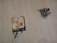
The latter two devices are ridiculously cheap and are ubiquitous on eBay and Amazon. The transmitter is a small 5mW laser. The receiver is an interesting little guy. It has an ISO203 sensor plunked on a board that is used for a thermal sensor. When illuminated, the output is low. When not illuminated, the output goes high. There’s a discussion of this device here: https://forum.arduino.cc/t/documents-about-laser-sensor-ds18b20/1090450 (scroll to the bottom for an explanation of the device.)
Typically, a beam interruption application has the laser receiver and transmitter pair always on, and the MCU code (on an Arduino, for example) in the loop() polls a pin attached to the output of the sensor. An alternative is to read the sensor output as an interrupt. In either scenario, the sensor, MCU, and transmitter are always powered on. Even if the output of the sensor to the MCU were used as an interrupt to wake a sleeping MCU, the laser requires approximately 25 mA continuously. That’s a lot for a battery-operated device that might get serviced once every two or three weeks.
However, if we are trying to detect low-frequency, long-duration events, continuous sampling of the laser beam is not needed. I’m not sure the Nyquist theorem is totally applicable, but it comes close. Let’s say it will take a human 0.2 seconds to walk through a doorway; the beam will be interrupted for 0.2 seconds. If we sample at twice that rate, we will detect the event. That means we turn on the laser and sensor ten times a second and do not leave the devices on continuously. If sampling can take place quickly, these power-hungry components have a very short duty cycle.
In practice, this works. The ESP32 is programmed to wake from deep sleep every 100 msec. A HIGH signal is sent to the logic level MOSFET (I love these things!!!), which then supplies power to the laser and sensor. The sensor output is read. If LOW, power to the sensor/laser is turned off and the MCU goes back to sleep. If the sensor output is HIGH, the MCU remains on. It continues to poll the sensor until the sensor is LOW. This approach prevents a single slow transit from being counted as multiple transits. Once the sensor is LOW, the event is processed. In my little experimental setup, this involved turning on an LED for a few hundred msec. In a real application, I’d likely access an external RTC running on a coin battery (like a DS3231 module with a CR2032 backup battery) to get a time stamp and then write to an SD card. The circuit then goes back to sleep. Both the laser and sensor are connected to the same MCU; a mirror is used to reflect the laser beam back to the sensor.
The power implications of this approach are considerable. The measured current draw with the MCU running and laser/sensor on is about 70 mA. The measured current draw with the MCU in deep sleep and laser/sensor off is about 3.5 mA. Removal of the power-on LED from the MCU board would reduce power consumption by at least another 1 mA. An on-power-up-read sensor cycle is approximately 60 microseconds. Let’s do a worst-case scenario and say that in real life, querying a DS3231 and writing to an SD card would take 100 msec and require 60 mA current (peripherals plus MCU). Finally, let’s assume that we are using my favorite rechargeable battery, the venerable 18650, and that 2000mAh are available. Although the laser devices call for 5V, the sensor and laser ran just fine directly from the battery at 3.7V. No need for level shifting or DC-DC converters.
With these assumptions, let’s do some back-of-the-envelope calculations. How many mAh will the device consume in 24 hrs, assuming 100 people per day go through the doorway?
I don’t know if someone has tried this before. If they have, kudos to them and I relinquish any claim to originality. However, if this is a new hack, I hope it is useful to someone. I acknowledge the utility of the ESP32 example code for deep sleep in the Arduino environment and the wonderful Random Nerd Tutorial on the subject, available here: https://randomnerdtutorials.com/esp32-deep-sleep-arduino-ide-wake-up-sources/
Final point. Mechanically, this is a difficult arrangement. The sensor target is tiny, and the laser beam is of narrow diameter (for heaven’s sake—it’s a laser!). Achieving (and maintaining) alignment of the beam and sensor has proven difficult. Even small vibrations associated with walking across a wooden bridge might cause misalignment. Weatherproofing, bug-proofing, and protection from ambient light would complicate construction as well. This is not a good candidate for outdoor use. However, I do think that the concepts involved are of value and might be applicable to other situations, such as an indoor doorway. I may try this with a SAMD21-based board and see if we do any better.
#define FETpin 32
#define LEDpin 23
#define SENSORpin 34
#define SENSEinterval 100000ULL //ten samples per second
long t1;
long t2;
//put in stuff to support a DS2321, programmed in another sketch and with a coin battery
void setup() {
pinMode( SENSORpin, INPUT); // sensor
pinMode( LEDpin, OUTPUT); //LED
pinMode( FETpin, OUTPUT); //FET pin
digitalWrite( LEDpin, LOW);
digitalWrite( FETpin, LOW);
//put in stuff to support a DS2321, programmed in another sketch and with a coin battery
esp_sleep_enable_timer_wakeup(SENSEinterval);
esp_sleep_pd_config(ESP_PD_DOMAIN_RTC_PERIPH, ESP_PD_OPTION_OFF);
digitalWrite(FETpin, HIGH);
delayMicroseconds(50);
if (digitalRead( SENSORpin) == HIGH) {
do { //keep cycling until beam is not interrupted
digitalWrite(FETpin, LOW);
delay(100); //delay 100 msec and see if beam is still interrupted
digitalWrite(FETpin, HIGH);
delayMicroseconds(50);
//when the beam is sensed again, exit loop and do something useful
} while (digitalRead( SENSORpin) == HIGH);
DoSomethingUseful();
digitalWrite( FETpin, LOW);
esp_deep_sleep_start();
}
else {
digitalWrite( FETpin, LOW);
esp_deep_sleep_start();
}
}
void DoSomethingUseful() {
digitalWrite(FETpin, LOW);
digitalWrite( LEDpin, HIGH);
delay(300);
digitalWrite( LEDpin, LOW);
//query an RTC (I like DS2321)
//write to SD card or flash memory
}
void loop() {
//loop is not used. Code executes from the beginning of setup each time the device awakens
}
The use case is to detect an individual (or perhaps a bicycle) traveling at low speed through a counting portal, such as a trailhead, doorway, or driveway. It is anticipated that traffic will be relatively light, perhaps anywhere between 20 and 100 events per day.
There are four core components:
- ESP32 Thing from Sparkfun or generic ESP32 board
- Logic level N MOSFET of your choice
- Laser sensor transmitter
- Laser sensor receiver
The latter two devices are ridiculously cheap and are ubiquitous on eBay and Amazon. The transmitter is a small 5mW laser. The receiver is an interesting little guy. It has an ISO203 sensor plunked on a board that is used for a thermal sensor. When illuminated, the output is low. When not illuminated, the output goes high. There’s a discussion of this device here: https://forum.arduino.cc/t/documents-about-laser-sensor-ds18b20/1090450 (scroll to the bottom for an explanation of the device.)
Typically, a beam interruption application has the laser receiver and transmitter pair always on, and the MCU code (on an Arduino, for example) in the loop() polls a pin attached to the output of the sensor. An alternative is to read the sensor output as an interrupt. In either scenario, the sensor, MCU, and transmitter are always powered on. Even if the output of the sensor to the MCU were used as an interrupt to wake a sleeping MCU, the laser requires approximately 25 mA continuously. That’s a lot for a battery-operated device that might get serviced once every two or three weeks.
However, if we are trying to detect low-frequency, long-duration events, continuous sampling of the laser beam is not needed. I’m not sure the Nyquist theorem is totally applicable, but it comes close. Let’s say it will take a human 0.2 seconds to walk through a doorway; the beam will be interrupted for 0.2 seconds. If we sample at twice that rate, we will detect the event. That means we turn on the laser and sensor ten times a second and do not leave the devices on continuously. If sampling can take place quickly, these power-hungry components have a very short duty cycle.
In practice, this works. The ESP32 is programmed to wake from deep sleep every 100 msec. A HIGH signal is sent to the logic level MOSFET (I love these things!!!), which then supplies power to the laser and sensor. The sensor output is read. If LOW, power to the sensor/laser is turned off and the MCU goes back to sleep. If the sensor output is HIGH, the MCU remains on. It continues to poll the sensor until the sensor is LOW. This approach prevents a single slow transit from being counted as multiple transits. Once the sensor is LOW, the event is processed. In my little experimental setup, this involved turning on an LED for a few hundred msec. In a real application, I’d likely access an external RTC running on a coin battery (like a DS3231 module with a CR2032 backup battery) to get a time stamp and then write to an SD card. The circuit then goes back to sleep. Both the laser and sensor are connected to the same MCU; a mirror is used to reflect the laser beam back to the sensor.
The power implications of this approach are considerable. The measured current draw with the MCU running and laser/sensor on is about 70 mA. The measured current draw with the MCU in deep sleep and laser/sensor off is about 3.5 mA. Removal of the power-on LED from the MCU board would reduce power consumption by at least another 1 mA. An on-power-up-read sensor cycle is approximately 60 microseconds. Let’s do a worst-case scenario and say that in real life, querying a DS3231 and writing to an SD card would take 100 msec and require 60 mA current (peripherals plus MCU). Finally, let’s assume that we are using my favorite rechargeable battery, the venerable 18650, and that 2000mAh are available. Although the laser devices call for 5V, the sensor and laser ran just fine directly from the battery at 3.7V. No need for level shifting or DC-DC converters.
With these assumptions, let’s do some back-of-the-envelope calculations. How many mAh will the device consume in 24 hrs, assuming 100 people per day go through the doorway?
- What’s the baseline sleep usage? If we assume 2 mA for 24 hours, that’s 48 mAh.
- The device turns on for 60 microseconds 10 times per second, using 70 mA while on. That means 600 us per second, 36000 us per minute, 2160000 us per hour, or 2.16 seconds per hour, times 24 or (rounding) 52 seconds per 24 hours. 52 seconds is 52/3600 of an hour, or .0144 hr. That means .0144 X 70 mA is just over 1 mAh. Now we’re up to 49 mAh.
- 100 people times 100 msec per person is 10 seconds per day processing events. 10 seconds is .003 hours X 60 mA is approx. .2mAh. Let’s round unfavorably and call the total 50 mAh per day.
- 40 days on a single charge! Clearly, the primary driving factor in power consumption is NOT processing events but sitting on standby. The use of an MCU that had an even lower deep sleep power consumption might well result in a longer battery life.
- Continuous on is easy: 70 mA x 24 is 1680 mAh, or under a day and a half.
I don’t know if someone has tried this before. If they have, kudos to them and I relinquish any claim to originality. However, if this is a new hack, I hope it is useful to someone. I acknowledge the utility of the ESP32 example code for deep sleep in the Arduino environment and the wonderful Random Nerd Tutorial on the subject, available here: https://randomnerdtutorials.com/esp32-deep-sleep-arduino-ide-wake-up-sources/
Final point. Mechanically, this is a difficult arrangement. The sensor target is tiny, and the laser beam is of narrow diameter (for heaven’s sake—it’s a laser!). Achieving (and maintaining) alignment of the beam and sensor has proven difficult. Even small vibrations associated with walking across a wooden bridge might cause misalignment. Weatherproofing, bug-proofing, and protection from ambient light would complicate construction as well. This is not a good candidate for outdoor use. However, I do think that the concepts involved are of value and might be applicable to other situations, such as an indoor doorway. I may try this with a SAMD21-based board and see if we do any better.
Code
#define FETpin 32
#define LEDpin 23
#define SENSORpin 34
#define SENSEinterval 100000ULL //ten samples per second
long t1;
long t2;
//put in stuff to support a DS2321, programmed in another sketch and with a coin battery
void setup() {
pinMode( SENSORpin, INPUT); // sensor
pinMode( LEDpin, OUTPUT); //LED
pinMode( FETpin, OUTPUT); //FET pin
digitalWrite( LEDpin, LOW);
digitalWrite( FETpin, LOW);
//put in stuff to support a DS2321, programmed in another sketch and with a coin battery
esp_sleep_enable_timer_wakeup(SENSEinterval);
esp_sleep_pd_config(ESP_PD_DOMAIN_RTC_PERIPH, ESP_PD_OPTION_OFF);
digitalWrite(FETpin, HIGH);
delayMicroseconds(50);
if (digitalRead( SENSORpin) == HIGH) {
do { //keep cycling until beam is not interrupted
digitalWrite(FETpin, LOW);
delay(100); //delay 100 msec and see if beam is still interrupted
digitalWrite(FETpin, HIGH);
delayMicroseconds(50);
//when the beam is sensed again, exit loop and do something useful
} while (digitalRead( SENSORpin) == HIGH);
DoSomethingUseful();
digitalWrite( FETpin, LOW);
esp_deep_sleep_start();
}
else {
digitalWrite( FETpin, LOW);
esp_deep_sleep_start();
}
}
void DoSomethingUseful() {
digitalWrite(FETpin, LOW);
digitalWrite( LEDpin, HIGH);
delay(300);
digitalWrite( LEDpin, LOW);
//query an RTC (I like DS2321)
//write to SD card or flash memory
}
void loop() {
//loop is not used. Code executes from the beginning of setup each time the device awakens
}
Updates des Autors