
Digital FM Receiver with Arduino and TEA5767
on
FM receivers are among the top popular circuits of any electronic enthusiast. In this article, I will introduce a complete digital FM receiver design that is equipped with an LCD screen and three push-buttons. It can search for FM signals in the range of 76 to 108 MHz and can be tuned manually and automatically (Scan mode). The signal strength is also displayed as a bar graph on the LCD. The output sound is amplified by a high-quality, powerful 3 W + 3 W Class-D stereo amplifier. To control the receiver, I used the inexpensive and popular Arduino Nano board.
FM Receiver Hardware
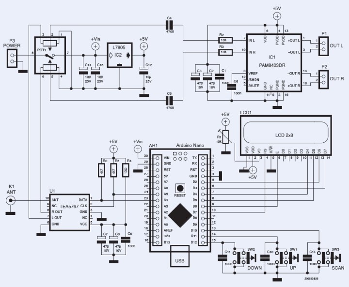
Figure 1 shows the schematic diagram of the device. The circuit consists of three main parts: the FM receiver module, the audio amplifier, and the digital section with the Arduino Nano that controls the device. Add a telescope antenna, a power supply, and two 8-Ω speakers to build this simple digital FM receiver.
Receiving the Radio Signal
The FM receiver module is based on the TEA5767; it is a well-known integrated circuit that can be controlled via the I2C bus. It covers the FM frequency range from 76 to 108 MHz and outputs L and R stereo audio channels that must be amplified. Even with an earphone, the audio signal level from the TEA5767 is too low. Frequency tuning and signal strength measurement are performed by the Arduino Nano code.
A low-pass RC filter (R4, C7, C8, and C9) reduces power supply noise. R5 and R6 are mandatory pull-up resistors for the I2C bus, and CON1 is a UFL connector that provides an antenna connection. Figure 2 shows the TEA5767 module.
The Audio Amplifier
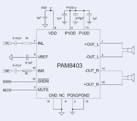
The PAM8403 is a 3 W + 3 W HiFi Class-D amplifier that can operate with only a single 5-V supply. The maximum output power can be achieved using 4-Ω speakers; however, for this project, 8-Ω speakers are recommended to limit power dissipation in the voltage regulator (IC2). According to the datasheet, “The PAM8403 is a 3 W, class-D audio amplifier. It offers low THD+N, allowing it to achieve high-quality sound reproduction. The new filter-less architecture allows the device to drive the speaker directly, requiring no low-pass output filters, thus saving the system costs and PCB area.”
C1, C2, and C3 are used for noise decoupling on the power supply pins, R2, R3, C4, and C5 are used to transfer the output audio to the amplifier. Also, they form high-pass RC filters to remove low-frequency noise. Figure 3 shows the reference circuit of the PAM8403 integrated circuit. P1 and P2 are right-angle two-pin XH connectors that are used to connect the speakers to the board. POT1 controls the output sound level.
Arduino in Control
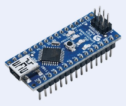
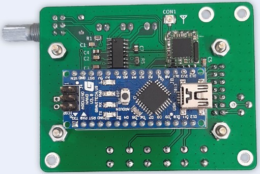
AR1, an Arduino Nano board (see Figure 4), is used to control this digital FM receiver. It drives a standard 8 x 2 character alphanumeric LCD (LCD1). It reads and reacts to the push buttons (SW1, SW2, and SW3), and sends/receives the TEA5767 data via the I2C bus. R1 sets the contrast level of the LCD and C10, C11, and C13 are used for switch debouncing.
Power Supply
The 7805 voltage regulator in D2PAK case is the main component of the power supply that provides a stable +5 V supply for the circuit. C12, C14, and C15 are used for noise decoupling, and the integrated switch of POT1 (the stereo volume potentiometer) powers the device on and off.

PCB Layout and Assembly
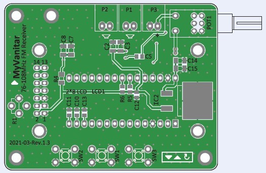
Figure 5 shows the PCB layout of the digital FM receiver. You can download the PCB’s Gerber and drill files of the author from the project’s page on the Elektor Labs website. You can order the board from your preferred supplier.
Even though most of the components on the PCB are SMD parts, soldering will not be too difficult with a small soldering iron and thin soldering wire. Start with the SMD components, take your time and check the solder joints of each component before continuing with the next one. Save the through-hole parts until last and pay close attention to which side of the PCB they should be soldered. The Arduino Nano board is mounted on the bottom side, and the LCD is on the top side of the board, preferably on socket strips. The correct orientation of the TEA5767 receiver is marked with a small rectangle on the PCB, depicting the crystal on the module.
Figure 6 shows the 3D views of the board, showing how this project is constructed.
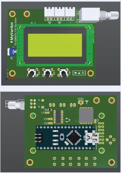
Figure 7 shows the high-quality fabricated PCBs of the digital FM receiver circuit.
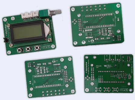
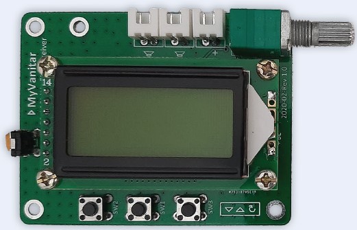
For reference, Figure 8 shows the assembled PCB from the top, and Figure 9 shows the bottom view of the assembled board.
You will also need four 5-mm spacers to fix the LCD on the PCB board. You should use a UFL-to-SMA-F connector to connect your antenna to the board. Figure 10 shows this type of connector.
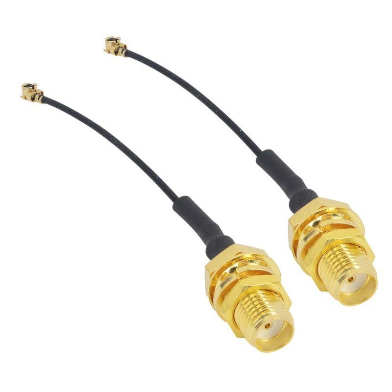
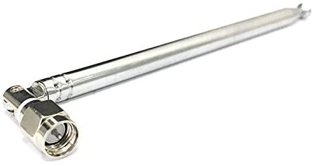
Figure 11 shows the telescopic antenna that can be connected.
Please note that an early version of the PCB is shown in Figures 6 to 9, but there are only minor differences with the final layout!
Arduino Code
The Arduino sketch for this FM receiver (FM_receiver.ino) is available for download at this project’s Elektor Labs page. The library for the LCD (LiquidCrystal) and the library for the I2C-bus (Wire) are supplied with the Arduino IDE. However, the TEA5767 library must be downloaded from GitHub and installed manually. Simply copy TEA5767.CPP and TEA5767.H into the folder where the sketch is saved. Just connect your Arduino Nano to the computer, and then compile and upload the code.
Operating the Receiver
The lower limit of the frequency is 76.0 MHz and the upper limit is 108.0 MHz. You can increase or decrease the frequency by 0.1 MHz by pressing the Up (SW1) and Down (SW2) buttons, respectively. Similarly, if you long-press these buttons, the frequency will be increased or decreased continuously. So, it is pretty easy to tune the receiver to your desired frequency (FM station). Moreover, with the Scan button (SW3) the receiver can automatically find FM stations with sufficient signal strength and lock the receiver on the frequencies. To search the next station, press the Scan button again.
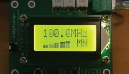
The FM signal strength is displayed on the LCD screen as a bar graph. To the right of this bar is an indication if the sound of the received station is either mono (“MN”) or stereo (“ST”). In Figure 12, the receiver is tuned to a powerful mono FM station at 100.0 MHz frequency.
This project can also be found on the Elektor Labs website, where the software, the PCB design, and Gerber files associated with this FM receiver are available for download. There is also a video on YouTube that shows how this FM receiver works.
COMPONENT LIST
Resistors
- R1 = 10 k trimmer, vertical style
- R2, R3 = 10k, size 0805
- R4 = 10 Ω, size 1206
- R5, R6 = 4.7 kΩ, size 0805
- POT1 = 50 kΩ stereo potentiometer + Switch (RV0971GS, see text)
Capacitors
- C1, C6, C9, C10, C11, C13 = 100 nF, size 0805
- C2, C3, C7, C8 = 47uF, size 1206
- C4, C5 = 470 nF, size 0805
- C12 = 10 uF, size 0805
- C14, C15 = 10 uF, size 1206
Semiconductors
- IC1 = 2 x 3 W audio amplifier PAM8403DR (SOIC-16)
- IC2 = 5 V voltage regulator MC7805CD2TG (D2PAK-style)
- U1 = FM Receiver module TEA5767
Miscellaneous
- AR1 = Arduino Nano board
- LCD1 = 2 x 8-character alphanumeric LCD
- P1, P2, P3 = 2-way XH-connector, 2.54 mm pitch
- SW1, SW2, SW3 = tactile push button 6 mm x 6 mm
- CON1 = UFL connector SMD + telescopic antenna (see text)
Discussion (6 comments)