In 2014, Elektor presented an interesting universal audio DSP board design. Based on the Analog Devices ADAU1701 DSP and through-hole components, the design was appealing to DIYers and audio enthusiasts. Refer to the circuit board design for the ADAU1701 Universal Audio DSP Board.
In 2014, Elektor presented an interesting universal audio DSP board design. Based on the Analog Devices ADAU1701 DSP and through-hole components, for DIYers and audio enthusiasts. Refer to the circuit board design for the ADAU1701 Universal Audio DSP Board.
The Board
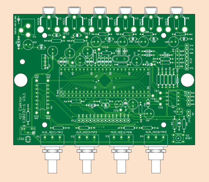
The board was supplied with the DSP chip pre-assembled, so the rest of the construction was meant to be fairly straightforward. Note that transistor T2 must not be fitted. It was required during an early phase of the project but could cause malfunction in the final setup.
The circuit board design.
The Schematic
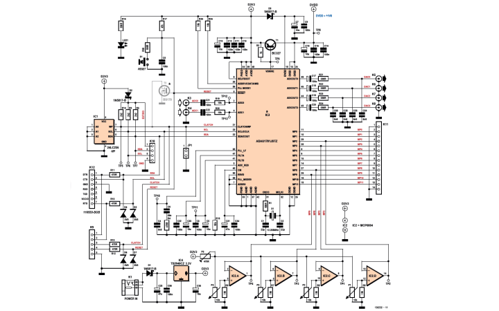
As you refer to the schematic, note that all the parts except the ADAU1701 DSP chip (IC3) are standard through-hole. Check it out.
"Unstabilized 5 to 12 volts DC enters the circuit via socket K1. Schottky diode D1 provides protection against reverse polarity of the input voltage. All other circuitry on the board operates off a 3.3 V voltage supplied by regulator IC4. The stereo analog input sound is applied to DSP audio inputs ADC0 and ADC1 via K3 and K4. The digitally processed audio from DAC0, DAC1, DAC2 and DAC3 is available on cinch connectors K5–K8. Pots P1, P2, P3 and P4 are analog inputs for the DSP. They deliver a voltage from 0 V to a maximum level defined by preset P5. The pot wiper voltages are buffered by rail-to-rail opamps IC2. A through IC2.D. Pushbutton S1 is used to reset the DSP via its RESET pin (5)."
Schematic of the ADAU1701 Audio DSP Board.
"Jumper JP1 on the DSP’s CLATCH line must be installed to program the on-board AT24CP EEPROM (IC1). Note that the DSP will not boot with JP1 fitted. After programming remove JP1 and press S1 to allow the DSP to boot. K10 is for programming the EEPROM using a special programmer. K12 allows using the Elektor FTDI-BOB module # 110553 to program the EEPROM using the Elektor application S.Studio to EEPROM Converter. This is rather slow though. K9 is for programming the EEPROM using custom hardware like an Arduino board."
Subscribe
Tag alert: Subscribe to the tag Circuits & Circuit Design and you will receive an e-mail as soon as a new item about it is published on our website!
"Its pins accept 5-V swing and are protected by 3.3 V zener diodes D6 and D7. K11 finally gives access to all GPIO pins of the DSP. Four lines (2, 3, 8, 9) are also used by the potentiometers P1-P4. Note however that these four lines can only be used to access the outputs of the opamp IC2, and not as inputs."
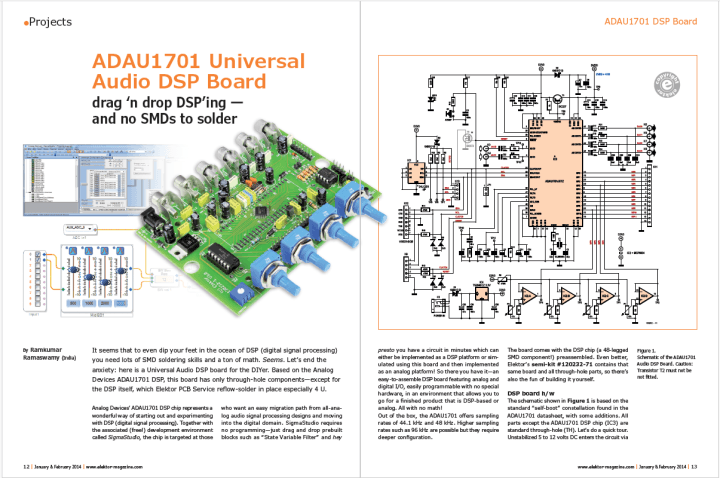
The article.
More About the Audio DSP Board
The article about this project appeared in Elektor 1/2 2014. Become a member to receive full access to Elektor’s complete library.
Subscribe
Tag alert: Subscribe to the tag DSP and you will receive an e-mail as soon as a new item about it is published on our website!
Read full article
Hide full article
Add a rating to this article
★★★★★
★★★★★
Page 1 / 1
Login
No account yet?Register for free!
Forgot password?
Please enter your email address. Instructions for resetting the password will be emailed to you now.


Discussion (4 comments)