
Activator for lead accumulators [160064]
Short high current pulses can prevent or even solve sulphating of the lead accumulators and can be used to measure its state of charge
https://youtu.be/fWQUtNQK-pY
Using high currents for a short time with accumulators can be used for 2 reasons. One is to prevent sulphating of the lead accumulators. A current pulse of about 100A during 100 μsec each 30 seconds is the optimum condition to prevent the sulphating of lead accumulators. But high currents give also the possibility to measure the state of charge SOC of an accumulator and/or battery.
A high current pulse will decrease the terminal voltage Vt of the accumulator or battery:
(V0-Vt)= I * Ri
with V0 the terminal voltage without load, I the load current and Ri the internal resistance. If one knows the shunt resistance then I= ΔVshunt/Rshunt, with ΔVshunt the potential over the shunt. The internal resistance can be calculated as:
Ri= Rshunt * (V0-Vt)/ΔV.
The three voltages voltage Vterminal, Vshunt-high, Vshunt-low are measured by means of 3 ADC’s of the microcontroller.
With a shunt resistance of 50 mΩ typical currents are 5A for single batteries and 130A for 12V lead accumulators. With these high currents the voltages has to be measured by separate lines. That means the shunt circuit should be isolated from the microcontroller circuit. Controlling the MOSFET gate an optocoupler is used and a DC-DC convertor produces the power for the gate. LCD and LED’s show the SOC parameters. For voltages > 5.5V the accumulator/battery powers both systems. At lower voltages a separate power is necessary for the microcontroller.
The project includes all lead accumulators 2V, 4V, 6V, 12V and 24V and all batteries and battery packs in the range from 0-30V
The schematic is relatively simple: R27 is the shunt resistor that is used for measuring/calculating the current sourced by the battery, which is connected to K3. D9 serves as reverse polarity protection, remember there is a diode inside T1 that will virtually short the battery if the connections are swapped. F1 is added to protect the battery and the circuit in case of failure (shorting) of T1.
The pulse circuit can be powered by the battery itself via D8 or (in case of low voltage batteries) via the optional DC-DC converter IC3. To ensure high current (in the range of 200A!) switching, the gate to source voltage of T1 must at least be 8V. The absolute maximum Vgs is 18V, R22 and Zener D10 limit Vgs to 15V. R21 is added the speed up switching off T1.
The gate of T1 is pulsed for 100µsec by an output of the microcontroller IC2 via optocoupler IC4. Depending on the setting of JP5 the pulses will be repeated every 10 of 30 seconds.
For measuring the battery voltage and current four-wire sensing is used, a method that is mostly used for current-sensing shunts. The current sourced by the battery will flow via K3, whereas the battery voltage will be measured at K1 (Vsense connections). K1 can also be used to power the circuit, for battery voltages below 5.5V an external power supply must be connected to K2.
There are three voltage dividers in the circuit, one for the battery terminal voltage Vt and the other two for measuring the voltage drop across the shunt (used to calculate the battery current). JP1 to JP4 are set to select one of three battery voltage ranges (i.e. 0-10V, 0-20V or 1-30V). All four jumpers must be set to the same position: either all four open (0-30V), closed in H position (0-20V) or closed in L position (0-10V). JP1 is read by the microcontroller’s software to determine which voltage range is selected.
Three analog inputs of the PIC18F1847 are used to measure the three voltages from the dividers, allowing the microcontroller to calculate and display the following results on the LCD:
V0: battery voltage (no load)
Vt: battery voltage during shunt load
I: current sourced by the battery during shunt load
R: battery’s internal resistance
LED1 will flash at the beginning of every current pulse. LED2 to LED4 give an extra indication of the actual battery voltage (without load), showing the state of charge of the battery:
Note: in the 0-10V range, at the start of the program the battery voltage is measured. Depending on this value it is determined what type of battery is connected (2V, 4V or 6V) and the thresholds for the LEDs are adjusted accordingly in software.
The microcontroller will also do some testing to check for realistic results and can -in some cases- determine faulty measurements of bad connections in the test circuit. In that case LED2 to LED4 will also indicate fault conditions:
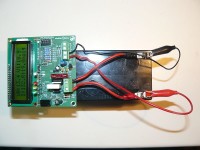
Constructing the circuit on the PCB we designed is rather straight-forward, in this design only through hole components. Special attention should be given to the shunt circuit on the PCB to reduce the total resistance, it is recommended to reinforce the traces between K3, D9, R27, T1 and F1 by soldering thick copper wires on the traces of the PCB. For that reason the soldermask on these traces is omitted in our PCB design. Also use thick and short (!) wires to connect the battery to K3.
BOM 160064-I
Resistor
R1,R25 = 10 kΩ, carbon film, 5%, 0.25W, 250V
R2,R3,R4,R5,R6,R7,R8,R9,R10,R11,R12,R13,R14,R15,R16,R17,R18,R19 = 22 kΩ, carbon film, 1%, 0.6W, 350V
R20,R21,R22 = 1 kΩ, carbon film, 5%, 0.25W, 250V
R23,R24 = 560 Ω, carbon film, 5%, 0.25W, 250V
R27 = 50mOhm 1W MPC75
R26 = 390 Ω, carbon film, 5%, 0.25W, 250V
P1 = 10 kΩ, trimmer, flat
Capacitor
C1 = 2.2 µF, 50 V, 2 mm pitch, 5x11 mm
C2,C8 = 10 µF, 50 V, 2 mm pitch, 5x11 mm
C3,C4,C5,C6 = 100 nF, 50 V, X7R, 5.08 mm pitch
Semiconductor
D1,D2,D7,D8 = BAT85, 30 V, 200 mA, Vf=400 mV @ If=10 mA
D3,D4,D5,D6 = zener diode 2V4, 500mW BZX79-C2V4
D9 = Schottky rectifier SR1204
D10 = BZX55C15V, 15 V, 500 mW
LED1 = LED, blue, 3 mm
LED2 = LED, red, 3 mm
LED3 = LED, yellow, 3 mm
LED4 = LED, green, 3 mm
T1 = N-MOSFET IRLB8721PBF, 62A, Rds 6.5mOhm
IC1 = LP2950ACZ-5.0, LDO, 5 V, 0.1 A
IC2 = PIC16F1847-I/P EPS 160064-41
IC3 = DC/DC converter 5V -> 15V RO0515S/P
IC4 = Optocoupler VO615A
Other
F1 = Fuseholder, PCB mount, ATO + fuse (see text)
LCD1 = 2 x 16 character LCD with backlight
LCD1 = 16-way pin header vertical, pitch 2.54mm
LCD1 = Pin socket, breakable, 1 row, 16-way, vertical
K1,K2 = Terminal block 5.08 mm, 2-way, 630 V
K3 = Terminal block 7.68 mm, 2-way, 630 V
JP1,JP2,JP3,JP4 = 3-way pin header vertical, pitch 2.54mm
JP5 = 2-way pin header vertical, pitch 2.54mm
n/a = Jumper for JP5, 2 way, 2.54 mm
Pin socket, breakable, 2 rows, 10-way, vertical (5 x 2-way jumper for JP1..JP5)
Misc.
PCB 160064-1 v2.1
n/a = IC socket, DIP-18
Using high currents for a short time with accumulators can be used for 2 reasons. One is to prevent sulphating of the lead accumulators. A current pulse of about 100A during 100 μsec each 30 seconds is the optimum condition to prevent the sulphating of lead accumulators. But high currents give also the possibility to measure the state of charge SOC of an accumulator and/or battery.
A high current pulse will decrease the terminal voltage Vt of the accumulator or battery:
(V0-Vt)= I * Ri
with V0 the terminal voltage without load, I the load current and Ri the internal resistance. If one knows the shunt resistance then I= ΔVshunt/Rshunt, with ΔVshunt the potential over the shunt. The internal resistance can be calculated as:
Ri= Rshunt * (V0-Vt)/ΔV.
The three voltages voltage Vterminal, Vshunt-high, Vshunt-low are measured by means of 3 ADC’s of the microcontroller.
With a shunt resistance of 50 mΩ typical currents are 5A for single batteries and 130A for 12V lead accumulators. With these high currents the voltages has to be measured by separate lines. That means the shunt circuit should be isolated from the microcontroller circuit. Controlling the MOSFET gate an optocoupler is used and a DC-DC convertor produces the power for the gate. LCD and LED’s show the SOC parameters. For voltages > 5.5V the accumulator/battery powers both systems. At lower voltages a separate power is necessary for the microcontroller.
The project includes all lead accumulators 2V, 4V, 6V, 12V and 24V and all batteries and battery packs in the range from 0-30V
The schematic is relatively simple: R27 is the shunt resistor that is used for measuring/calculating the current sourced by the battery, which is connected to K3. D9 serves as reverse polarity protection, remember there is a diode inside T1 that will virtually short the battery if the connections are swapped. F1 is added to protect the battery and the circuit in case of failure (shorting) of T1.
The pulse circuit can be powered by the battery itself via D8 or (in case of low voltage batteries) via the optional DC-DC converter IC3. To ensure high current (in the range of 200A!) switching, the gate to source voltage of T1 must at least be 8V. The absolute maximum Vgs is 18V, R22 and Zener D10 limit Vgs to 15V. R21 is added the speed up switching off T1.
The gate of T1 is pulsed for 100µsec by an output of the microcontroller IC2 via optocoupler IC4. Depending on the setting of JP5 the pulses will be repeated every 10 of 30 seconds.
For measuring the battery voltage and current four-wire sensing is used, a method that is mostly used for current-sensing shunts. The current sourced by the battery will flow via K3, whereas the battery voltage will be measured at K1 (Vsense connections). K1 can also be used to power the circuit, for battery voltages below 5.5V an external power supply must be connected to K2.
There are three voltage dividers in the circuit, one for the battery terminal voltage Vt and the other two for measuring the voltage drop across the shunt (used to calculate the battery current). JP1 to JP4 are set to select one of three battery voltage ranges (i.e. 0-10V, 0-20V or 1-30V). All four jumpers must be set to the same position: either all four open (0-30V), closed in H position (0-20V) or closed in L position (0-10V). JP1 is read by the microcontroller’s software to determine which voltage range is selected.
Three analog inputs of the PIC18F1847 are used to measure the three voltages from the dividers, allowing the microcontroller to calculate and display the following results on the LCD:
V0: battery voltage (no load)
Vt: battery voltage during shunt load
I: current sourced by the battery during shunt load
R: battery’s internal resistance
LED1 will flash at the beginning of every current pulse. LED2 to LED4 give an extra indication of the actual battery voltage (without load), showing the state of charge of the battery:
| Range | 0-10V | 0-10V | 0-10V | 0-20V | 0-30V |
| V0 | V0<2.5V | 2.5V |
5V |
||
| 2V battery | 4V battery | 6V battery | 12V battery | 24V battery | |
| red | <1.98V | <4V | <5.95V | <11,9V | <23.8V |
| yellow | 1.89-2.08V | 4.00-4.16V | 5.95-6.25V | 11.9-12.5V | 23.8-25V |
| green | >2.08V | >4.16V | >6.25V | >12.5V | >25V |
Note: in the 0-10V range, at the start of the program the battery voltage is measured. Depending on this value it is determined what type of battery is connected (2V, 4V or 6V) and the thresholds for the LEDs are adjusted accordingly in software.
The microcontroller will also do some testing to check for realistic results and can -in some cases- determine faulty measurements of bad connections in the test circuit. In that case LED2 to LED4 will also indicate fault conditions:
| flash rate | action required | ||
| Possibly open circuit | green | slow (1s) | check and correct connections |
| No battery | green | fast (400ms) | check connections or external power supply needed |
| Voltage out or range | yellow | fast (400ms) | disconnect battery immediately |
| Current too high | red | fast (400ms) | Add external series resistor to the shunt circuit |
Constructing the circuit on the PCB we designed is rather straight-forward, in this design only through hole components. Special attention should be given to the shunt circuit on the PCB to reduce the total resistance, it is recommended to reinforce the traces between K3, D9, R27, T1 and F1 by soldering thick copper wires on the traces of the PCB. For that reason the soldermask on these traces is omitted in our PCB design. Also use thick and short (!) wires to connect the battery to K3.
BOM 160064-I
Resistor
R1,R25 = 10 kΩ, carbon film, 5%, 0.25W, 250V
R2,R3,R4,R5,R6,R7,R8,R9,R10,R11,R12,R13,R14,R15,R16,R17,R18,R19 = 22 kΩ, carbon film, 1%, 0.6W, 350V
R20,R21,R22 = 1 kΩ, carbon film, 5%, 0.25W, 250V
R23,R24 = 560 Ω, carbon film, 5%, 0.25W, 250V
R27 = 50mOhm 1W MPC75
R26 = 390 Ω, carbon film, 5%, 0.25W, 250V
P1 = 10 kΩ, trimmer, flat
Capacitor
C1 = 2.2 µF, 50 V, 2 mm pitch, 5x11 mm
C2,C8 = 10 µF, 50 V, 2 mm pitch, 5x11 mm
C3,C4,C5,C6 = 100 nF, 50 V, X7R, 5.08 mm pitch
Semiconductor
D1,D2,D7,D8 = BAT85, 30 V, 200 mA, Vf=400 mV @ If=10 mA
D3,D4,D5,D6 = zener diode 2V4, 500mW BZX79-C2V4
D9 = Schottky rectifier SR1204
D10 = BZX55C15V, 15 V, 500 mW
LED1 = LED, blue, 3 mm
LED2 = LED, red, 3 mm
LED3 = LED, yellow, 3 mm
LED4 = LED, green, 3 mm
T1 = N-MOSFET IRLB8721PBF, 62A, Rds 6.5mOhm
IC1 = LP2950ACZ-5.0, LDO, 5 V, 0.1 A
IC2 = PIC16F1847-I/P EPS 160064-41
IC3 = DC/DC converter 5V -> 15V RO0515S/P
IC4 = Optocoupler VO615A
Other
F1 = Fuseholder, PCB mount, ATO + fuse (see text)
LCD1 = 2 x 16 character LCD with backlight
LCD1 = 16-way pin header vertical, pitch 2.54mm
LCD1 = Pin socket, breakable, 1 row, 16-way, vertical
K1,K2 = Terminal block 5.08 mm, 2-way, 630 V
K3 = Terminal block 7.68 mm, 2-way, 630 V
JP1,JP2,JP3,JP4 = 3-way pin header vertical, pitch 2.54mm
JP5 = 2-way pin header vertical, pitch 2.54mm
n/a = Jumper for JP5, 2 way, 2.54 mm
Pin socket, breakable, 2 rows, 10-way, vertical (5 x 2-way jumper for JP1..JP5)
Misc.
PCB 160064-1 v2.1
n/a = IC socket, DIP-18
Updates vom Autor